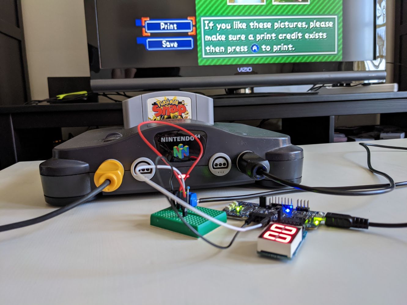
Back in 1999 when the original Pokémon Snap was released for the Nintendo 64, one of its coolest features was that you could print out the photos you took in-game on sticker sheets using a Snap Station. Snap Stations could only be found at a Blockbuster video store (or a Lawson convenience store in Japan), and you’d have to pay for credits in the form of Pokémon-styled smart cards each time you wanted to print out a sheet of stickers. I’ve had one of the Charmander cards sitting around with my collection of Nintendo stuff for a while, which got me thinking about what it would be like to hack one of these kiosks.
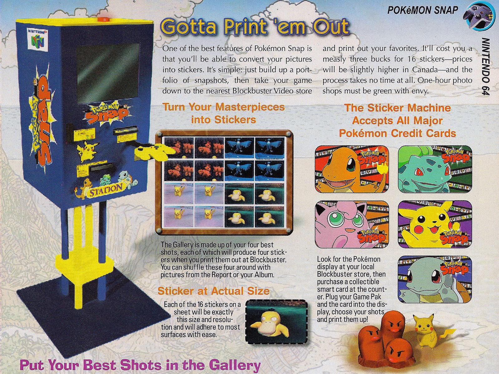
The Snap Stations themselves are hard to come by these days, but while watching some YouTube videos made by collectors I recalled that, in order to print your photos, you would insert your own Pokémon Snap game cartridge into the station. Furthermore, some videos showing the interior of the station revealed that the printer hardware was actually connected to the Nintendo 64 through its fourth controller port. That suggested that the code for handling some amount of the printing behavior might be present on all retail copies of the game.
By looking into the Pokémon Snap ROM, I was able to quickly confirm that the print menu text was present in the retail copy of the game:
a08270 63 72 65 65 6e 2e 00 00 49 66 20 79 6f 75 20 6c  >creen...If you l<
a08280 69 6b 65 20 74 68 65 73 65 20 70 69 63 74 75 72  >ike these pictur<
a08290 65 73 2c 20 70 6c 65 61 73 65 0a 6d 61 6b 65 20  >es, please.make <
a082a0 73 75 72 65 20 61 20 70 72 69 6e 74 20 63 72 65  >sure a print cre<
a082b0 64 69 74 20 65 78 69 73 74 73 0a 74 68 65 6e 20  >dit exists.then <
a082c0 70 72 65 73 73 20 5c 61 20 74 6f 20 70 72 69 6e  >press \a to prin<
a082d0 74 2e 00 00 52 65 74 75 72 6e 20 74 6f 20 74 68  >t...Return to th<
a082e0 65 20 54 69 74 6c 65 20 53 63 72 65 65 6e 0a 62  >e Title Screen.b<
a082f0 79 20 73 61 76 69 6e 67 2e 00 00 00 47 61 6c 6c  >y saving....Gall<
It was much trickier to identify the actual code responsible for handling the print functionality for reasons I’ll describe later, but with a combination of static analysis, dynamic analysis, and a custom FPGA-based hardware tool, I was able to reverse engineer the Snap Station’s control protocol without having access to one. (With access to a real Snap Station, all I would’ve had to do was use a logic analyzer to observe what was being transmitted over the fourth controller port.)
Using this information, I’ve implemented a Snap Station simulator in the Project64 emulator, as well as a hardware implementation using an iCEBreaker FPGA board. The code for each can be found at:
- Project64 fork: https://github.com/jamchamb/project64/tree/snapstation
- iCEBreaker/iCE40UP5k FPGA design: https://github.com/jamchamb/cojiro
The following video shows the Snap Station simulator in Project64:
I recommend watching a video of the real Snap Station in action if you haven’t yet in order to help make sense of what happens at the end.
When the player presses the Print button, the selection of photos chosen for printing is saved to the game cartridge. The station then resets the console and instructs the game to enter a photo display mode after the boot logo screen. The printer in the Snap Station uses a video pass-through input to capture photos directly from the Nintendo 64’s video output. Each time a photo is displayed, the station instructs the printer to perform a screen capture. After all 16 photos have been displayed and captured the station can print out the sticker sheet.
The end result doesn’t look like much without any printer hardware involved, but using the FPGA design I’ve released, you could implement a full setup with a printer if you really wanted to. The big takeway for me with this project was learning how to reverse engineer and simulate peripherals with an FPGA.
Snap Station protocol summary
The Snap Station protocol itself is pretty simple, and I will briefly describe how it works before going into the details of how I reverse engineered it.
The Snap Station acts like a controller with a peripheral plugged into it, much like a Rumble Pak or Controller Pak (memory card). Communication happens via the same read and write commands used by the Controller Pak, which read or write 32 bytes of data at a specified address. In this case the address indicates the type of message rather than an actual memory location.
To signal to the game that printing functionality is enabled, the station indicates a peripheral is plugged in. This causes the game to start querying what type of peripheral is connected through the controller. These messages use the address 0x8000:
write cmd: 8000 (addr CRC-5 01)
  fe fe fe fe fe fe fe fe fe fe fe fe fe fe fe fe
  fe fe fe fe fe fe fe fe fe fe fe fe fe fe fe fe
  response: e1
read cmd: 8000 (addr CRC-5 01)
  response: 00 00 00 00 00 00 00 00 00 00 00 00 00 00 00 00
            00 00 00 00 00 00 00 00 00 00 00 00 00 00 00 00
            00
write cmd: 8000 (addr CRC-5 01)
  85 85 85 85 85 85 85 85 85 85 85 85 85 85 85 85
  85 85 85 85 85 85 85 85 85 85 85 85 85 85 85 85
  response: f5
read cmd: 8000 (addr CRC-5 01)
  response: 85 85 85 85 85 85 85 85 85 85 85 85 85 85 85 85
            85 85 85 85 85 85 85 85 85 85 85 85 85 85 85 85
            f5
The console first sends a message with repeating FE bytes, which is something like a reset or initialization message, followed by 85 repeating, which is the peripheral ID it’s checking for. The station should respond with 85, where a different device like the Rumble Pak would respond with 80. If this happens during the initial boot screen, the game goes into the photo display mode. Otherwise it just registers that the station is available, which enables the Print button in the Gallery.
Messages that correspond to the state of the print flow use the address 0xC000. When the player presses the Print button in the Gallery menu, the following values are sent to station:
read cmd: C000 (addr CRC-5 1b)
  response: 00 00 00 00 00 00 00 00 00 00 00 00 00 00 00 00
            00 00 00 00 00 00 00 00 00 00 00 00 00 00 00 00
            00
write cmd: C000 (addr CRC-5 1b)
  00 00 00 00 00 00 00 00 00 00 00 00 00 00 00 00
  00 00 00 00 00 00 00 00 00 00 00 00 00 00 00 cc
  response: 27
read cmd: C000 (addr CRC-5 1b)
  response: 00 00 00 00 00 00 00 00 00 00 00 00 00 00 00 00
            00 00 00 00 00 00 00 00 00 00 00 00 00 00 00 cc
            27
read cmd: C000 (addr CRC-5 1b)
  response: 00 00 00 00 00 00 00 00 00 00 00 00 00 00 00 00
            00 00 00 00 00 00 00 00 00 00 00 00 00 00 00 cc
            27
write cmd: C000 (addr CRC-5 1b)
  00 00 00 00 00 00 00 00 00 00 00 00 00 00 00 00
  00 00 00 00 00 00 00 00 00 00 00 00 00 00 00 33
  response: aa
read cmd: C000 (addr CRC-5 1b)
  response: 00 00 00 00 00 00 00 00 00 00 00 00 00 00 00 00
            00 00 00 00 00 00 00 00 00 00 00 00 00 00 00 33
            aa
read cmd: C000 (addr CRC-5 1b)
  response: 00 00 00 00 00 00 00 00 00 00 00 00 00 00 00 00
            00 00 00 00 00 00 00 00 00 00 00 00 00 00 00 33
            aa
write cmd: C000 (addr CRC-5 1b)
  00 00 00 00 00 00 00 00 00 00 00 00 00 00 00 00
  00 00 00 00 00 00 00 00 00 00 00 00 00 00 00 5a
  response: 59
read cmd: C000 (addr CRC-5 1b)
  response: 00 00 00 00 00 00 00 00 00 00 00 00 00 00 00 00
            00 00 00 00 00 00 00 00 00 00 00 00 00 00 00 5a
            59
Only the last data byte of each message matters, so in short the sequence is:
0xCC0x330x5A
There isn’t much meaning to the values themselves, they’re just bit patterns (1100 1100, 0011 0011, and 0101 0101). The first two (CC, 33) are sent before and after the save operation is performed, which saves the selected photos for printing. The last one (5A) signals that it’s time to do a soft reset on the console, which I believe was handled in the Snap Station by directly triggering the console’s reset button or cycling the power.
The station remains active during the reset, so it will be present during the Nintendo logo boot screen, which triggers the photo display mode. In this mode, the console sends the following bytes to the 0xC000 address:
0x010x02(16 times in a row)0x04
Knowing that 16 photos are displayed, it’s easy to guess that 01 signals the start of the display, 02 is sent each time a photo is displayed, and 04 signals the end of the display (when the screen goes blank).
At any point during the communications with the C000 address the station can return a value of 08 to trigger a busy loop, which can help synchronize the state of the station and the game code. In the gallery menu, I’ve used this to keep the game frozen at the 5A message until the console has been reset, which keeps the “Now Saving…” message displayed while the Print button is darkened. If the game were to proceed past reading 5A back, the player would just remain in the Gallery menu and nothing would appear to happen, which looks awkward. In the photo display mode I use the busy loop to keep the photos displayed a little longer so that they don’t flash by too quickly. With a real printer involved in the setup, these pauses could help ensure that each photo is captured and stored in the print buffer.
Take a look at the Source/Project64-core/N64System/Mips/Snapstation.cpp file in the Project64 fork linked above to see how this is described in code.
Reverse engineering
Static analysis difficulties
The toughest part of this project was simply finding code relevant to the Snap Station within the Pokémon Snap ROM. Disassembling the game code was complicated due to code moving around at runtime, with some mutually exclusive segments of code even occupying the same areas of memory when navigating through different menus or gameplay. Most of this was probably due to the use of overlays, a technique for conserving RAM where “some segments share the same memory region during different phases of execution.” This caused most of the automatic disassembly to fail, because the addresses of the code as loaded into the disassembler didn’t match where they would be at runtime. Disassemblers generally perform automatic code discovery by following jump instructions, which wouldn’t work here.
Besides a couple of debug and error strings, there were no symbol names to work with. Without the benefit of accurate cross-reference information for code and data, this made it very hard to build up any context with static analysis, which is crucial for understanding complex code without any metadata information about it. I was able to to configure the memory layout in Ghidra to get one decent chunk of code to disassemble correctly, but loading the entire game ROM properly would’ve been an intensive task.
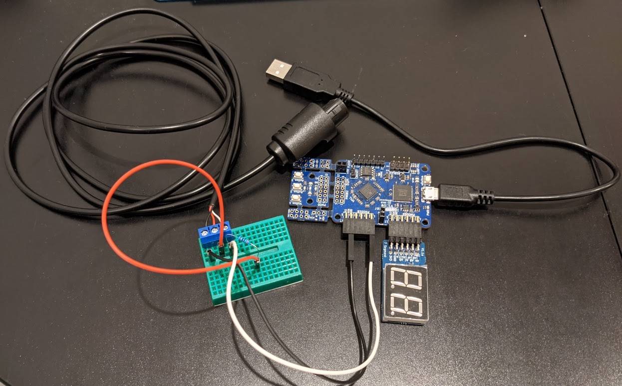
JoyBus FPGA tool
At this point I decided to switch over to working on the FPGA-based hardware interface for the JoyBus protocol used by Nintendo 64 controllers in the hopes that probing the controller port would provide quicker results. There are a few good resources with unofficial documentation on how JoyBus works online; in particular I found https://sites.google.com/site/consoleprotocols/home/nintendo-joy-bus-documentation helpful. Here’s a quick recap of how the hardware interface works:
- There’s one bi-directional data line used by the console and controller to communicate with each other. The other two pins in a controller port are power and ground.
- The data line is an “open drain” output. This means the line is held at the high logic level by default, and devices on the bus communicate by pulling the line down to ground. For the FPGA implementation this means the JoyBus pin will be left in high impedance mode except when transmitting a 0 bit.
- A pull-up resistor on the data line helps the signal rise back to the high logic level faster, resulting in a more square waveform.
- Every bit transmission starts with pulling the line low for a microsecond, holding it at high for a 1 bit or low for a 0 bit for two microseconds, and always returning high for the fourth microsecond. That’s four microseconds per bit, so the bit rate is roughly 250,000 bits per second.
For the physical connection to the console I cut an N64 controller extension cable in half and broke the wires out to a breadboard. Besides some jumper cables to connect to the iCEBreaker, the only other component on the breadboard is a 330 Ohm pull-up resistor between the 3.3V power line and the data line.
Console commands consist of a one byte command ID followed by optional data bytes, such as a 16-bit read address for the Controller Pak read command. I started by implementing the two basic commands needed to simulate a regular N64 controller. The first (FF or 00) queries the type of device connected and its status, and the second (01) checks the current state of the buttons and analog stick.
I connected the iCEBreaker to the fourth controller port while Pokémon Snap was running and tried returning different values to the query command to see if different device type IDs or status values would be recognized. With the normal controller ID 0500, just changing the status to 01 to indicate a peripheral was plugged in caused the console to send a few more requests to the device. At the time I noticed this by watching an oscilloscope hooked up to the data line; to get a better look at the data I added UART forwarding to send the request packets over to my PC. With the UART forwarding I was able to see the write command with the FEFEFEFE... payload:
03 8001 fefefefefefefefefefefefefefefefefefefefefefefefefefefefefefefefe
Knowing that reporting a controller with a peripheral plugged in on the fourth port did something interesting, I switched back to dynamic analysis with the Project64 emulator to see if I could identify code that checked the status of the fourth controller.
Dynamic analysis
Using the Project64 debugger to set watchpoints on reads or writes to the controller state memory was fruitless because they were constantly triggered by code that I assume was generic system-level code checking and updating the controller state every frame.
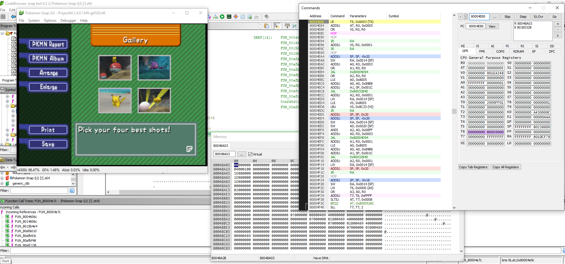
Instead I tried a more indirect approach with memory scanning on the Gallery menu. First I tracked down the location of the current button index with the standard technique of repeatedly updating the selection and then scanning memory for the newly changed value. Then I could set read watchpoints on the button index value to see if I could identify where the menu handling code was.
Initially this also caused the watchpoint to trigger repeatedly. By patching out the read instruction that was repeatedly triggered, I saw it was caused by the glowing orange cursor that shows above the currently selected button. After removing that read instruction I got much more useful results: the watchpoint triggered when the menu description text for the currently selected button was changed, and when I pressed A to trigger the currently selected button.
With this approach I was finally able to find that, in the menu code, there were some conditional checks related to the button index where the Print button would appear (6, right before the Save button which has index 7). One of the checks was a call to a function that simply checked if a certain global variable had a value of 5. On a hunch that this was some kind of state related to printing, I patched the function to always return true, which resulted in the Print button appearing:
Tracking down the code that would set this particular variable to 5 finally led me to the code that appeared to send out the FE and 85 sequences on the JoyBus. Looking at the code, I could see that for the first command the controller should not return FE in kind, and for the second it should return back the repeating 85 sequence. Implementing this behavior on the FPGA unlocked the core behavior of enabling the Print button and triggering the photo display mode when the game first boots. With the UART forwarding feature, the rest of the protocol became evident when pressing the Print button or during the photo display, and with a little more reversing I found what the messages sent from the Gallery menu meant and how to trigger the busy loops by returning a value of 8.
Conclusion
For the final FPGA tool setup, I use a button for advancing the state of the station. The first button press enables the station, which helps avoid launching immediately into the photo display when you start the game. Next it waits to receive the 5A message and maintains a busy loop to keep the “Now Saving…” message displayed until the player resets the console manually. Once the console reboots into the photo display, pressing the button will advance the photo display one at a time until all 16 photos are displayed.