I started this project because I wanted to be able to use save file modifications I was testing in the Dolphin emulator on real GameCube hardware. One, because some of the weirder features of the Animal Crossing NES emulator and exploit payloads might behave differently in an emulator, and two, because it’s more fun to see things working on a real console.
While it’s possible to transfer files between a PC and memory card using an “SDGecko” SD adapter and homebrew software on a Wii (or GameCube with something like the SD Launcher kit), I don’t have a Wii and it seemed like overkill to buy these things just to edit memory cards. There’s also this obscure GameCube memory card with a built-in USB adapter that allowed editing with custom PC software, but it seems like it went out of production a while ago.
Instead of hunting down out-of-print adapters or buying another console just to transfer some files, I thought it would be an interesting hardware reverse engineering project to figure out how GameCube memory cards work, and how I could simulate or edit them.
The first steps to understanding how the memory card works are:
- Mapping out the physical interface between the memory card and console
- Capturing electrical signals transmitted between the console and memory card to figure out the low level transmission protocol
- Capturing transmitted data
- Interpreting captured data to figure out the format of commands that the console sends to the memory card to perform read and write operations
After understanding how read and write commands are sent to the memory card, and how the memory card should respond, it will be possible to simulate a memory card or edit it directly.
Physical interface
Luckily there are already some diagrams of the memory card’s pins, such as in this post on the GC-Forever forum by Ashen: https://www.gc-forever.com/forums/viewtopic.php?t=666.
The first row of pins that enters the console are for power and ground connections. The second row has all of the pins involved in data transfer, and there’s also a “sense” pin in each row so that the console can tell when the card is plugged all the way in.
Here’s what the inside of a third-party memory card looks like, with the pins and main components labelled:
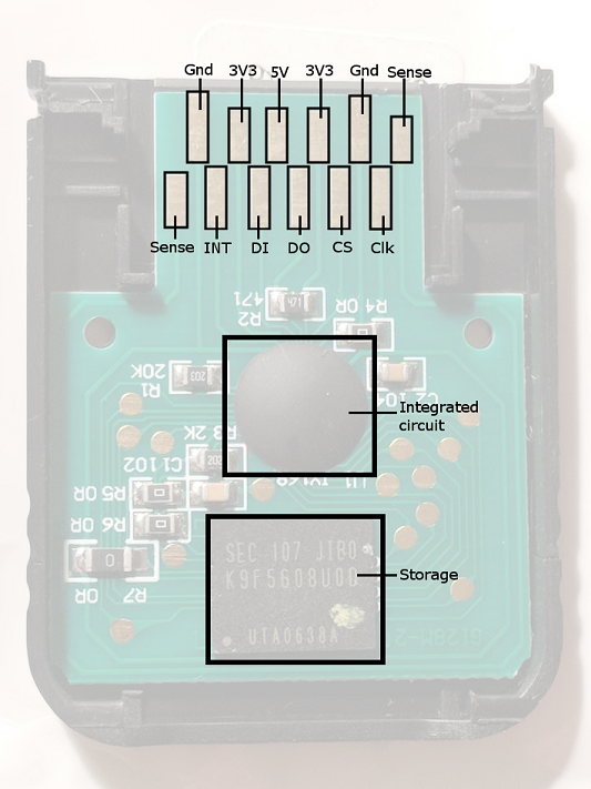
I assumed DI and DO stood for data in/data out, and the clock was the clock signal. INT and CS were less clear, as there was no protocol described to give context, but I guess that INT stands for interrupt, and CS is the “chip select” pin from SPI.
Capturing signals
To figure out what exactly these pins are used for and what the protocol is, I’d have to have some way to capture the signal going through them while the GameCube accesses the memory card.
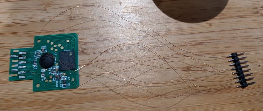
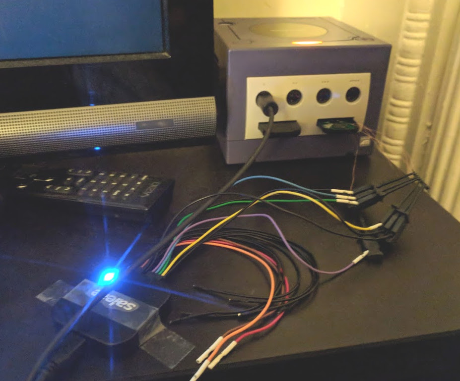
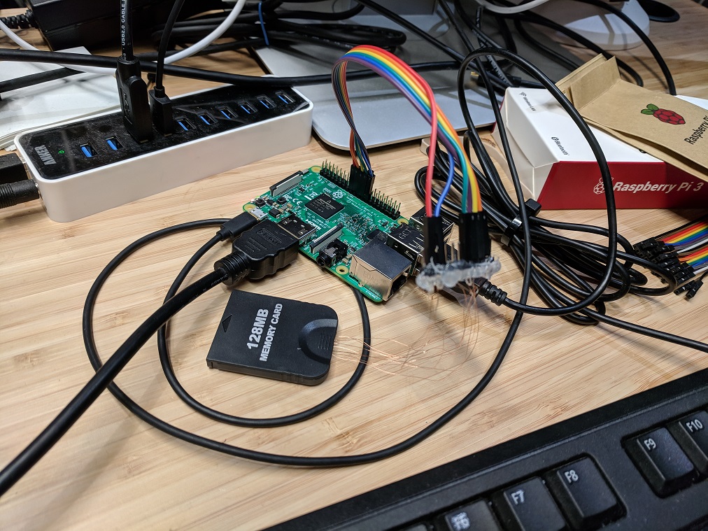
To do this I soldered some thin enameled wire to each of the pins on the bottom row (DI, DO, CS, INT, CLK). Here’s how the first attempt turned out:
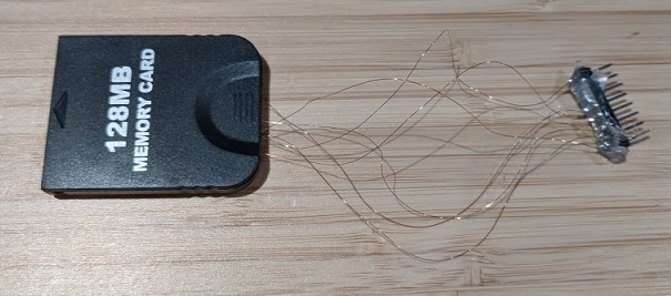
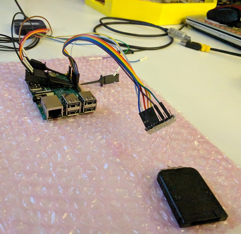
This card stopped getting a clean signal after a while, so the second time around I kept the wires shorter with more consistent lengths, and added some extra hot glue for support:
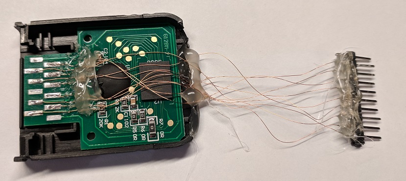
(Note that I also added wires to the power and ground pins - this was for directly connecting to the card from a Raspberry Pi later on.)
It’s a bit tricky to solder this up, and if you’re just looking to make the memory card editor it would be much cleaner to use a spare memory card slot from an actual console.
With the pins wired up, I could finally capture the signal from them using a logic analyzer. I used a saleae Logic 8 and connected to all of the data row pins, and then performed captures while doing things like inserting the card or copying and deleting files with the system memory card manager.
Besides INT, the data pins map neatly to the standard SPI channels, and using the SPI analyzer turned up a byte stream without much fuss:
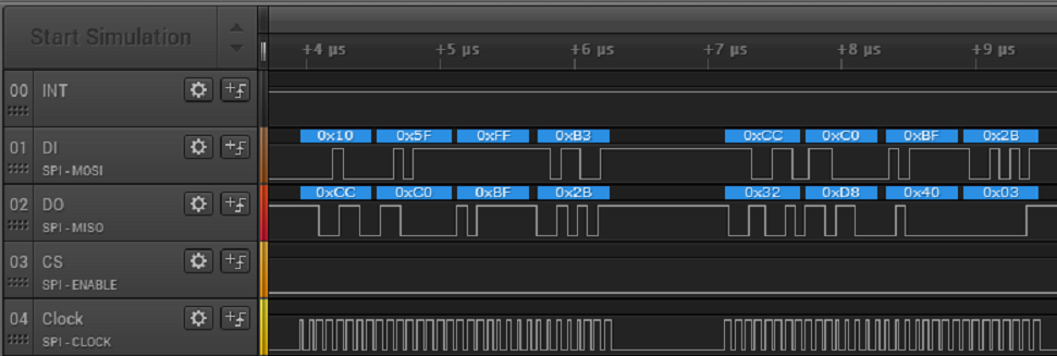
- DI - MOSI
- DO - MISO
- CS - CS / Enable
- Clock - Clock
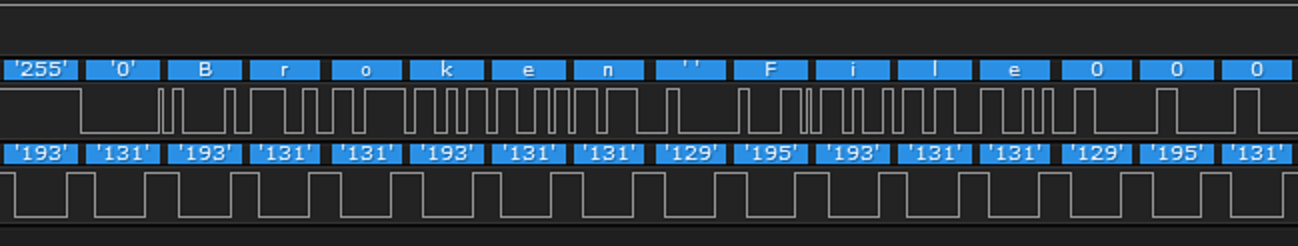
This bit of ASCII text that says “Broken File” appearing in the data stream from the card made it easy to check that the settings were correct:
Now it’s clear that the communication protocol is almost entirely standard SPI, save for the INT pin. (If you’re not familiar with SPI, this Sparkfun tutorial is a good resource: https://learn.sparkfun.com/tutorials/serial-peripheral-interface-spi/all.) Luckily the INT pin doesn’t appear to do much, and its signal doesn’t change often, so you don’t need to worry about it just yet.
Reading the traffic
With the low level transmission protocol figured out, it was time to figure out what the bytes being sent between the console and memory card meant. The first thing I wanted to figure out was the read commands so that I’d be able to copy out the contents of the card, whether directly or from a logic analyzer dump.
The “Yet Another Gamecube Documentation” (YAGCD) memory card section, while incomplete, was helpful for identifying the main commands.
For example, “read block” commands start with 0x52 and an offset address.
Here’s the beginning of a command to read the first block, at offset zero:
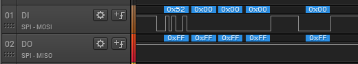
After that there are 128 filler bytes with the value 0xFF (possibly to give the card time
to start reading), and finally the card will
begin to return data beginning from the requested offset as long as the console continues
reading. Write commands are similar: they begin with 0xF2 and an offset address, and
then continue with bytes to be written starting from that offset.
When a card is inserted in the console while using the memory card manager, all of the data blocks will be read. By writing a simple parser in Python I was able to reconstruct most of the content of my memory card by using the read commands and responses from a logic analyzer dump of this process.
Interfacing with card on Raspberry Pi
To read all of the contents of the memory card flash, and to start sending my own write commands to it, I’d need to interface directly with the card from hardware that I could program. This is where the Raspberry Pi comes in. It has some dedicated SPI pins that can be used via the Linux spidev interface. This allows me to write a program that will act like the console (SPI master) to the memory card.
Connecting the card to the RasPi requires adding the 3.3V power and ground pins, as seen in the picture of the second card I soldered, and connecting the dedicated SPI pins to the corresponding memory card pins.
- RasPi SPI Clock -> Clock
- RasPi SPI MOSI -> DI
- RasPi SPI MISO -> DO
- RasPi SPI CS -> CS
I wrote a simple program in Python that used a Python spidev library to read each block from the card. To get a reliable read you need to use a clock speed that the RasPi and memory card can handle. The average clock speed used by the console is 12.5 MHz, so I’ve been using 12 MHz as the clock speed.
It takes a little while to read every single block, but it worked and I was able to reliably read all the data out of the card. This also happened to reveal the source of the flash chips used on these third-party memory cards from Amazon: all of the ones I’ve looked at have leftover firmware for some Super-H based TV related device on them.
The final step was to implement write commands, as well as a few minor commands related to getting and setting the status of the card. I encountered a pretty painful bug at this point: I would send over a bunch of write commands, read the data back, and see that nothing changed. The first thing I tried was setting up an extra GPIO pin on the RasPi to use as the INT pin. It wasn’t necessary for getting read commands to work, but I thought maybe it was required for writes. That still didn’t fix it.
Finally, I hooked the logic analyzer up to the Raspberry Pi to debug my SPI traffic:
It turns out that I just never added the data I meant to send to the write command buffers! After fixing that, it still behaved oddly: only the first write command would work. This time I had to tweak the timing between commands, as well as use of the INT pin and status commands, to get all of the write commands to work in sequence.
The code is a little rough, but I’ve made it available at https://github.com/jamchamb/gc-memcard-adapter.
I had orignally planned to directly simulate memory cards with a Raspberry Pi after figuring out the communication protocol, but it turns out that it’s only practical to use as the SPI master (it’s possible to “bit bang” this without the direct SPI hardware support, but it would be too slow to meet the required 12.5 MHz clock speed). I’ll have to look at some other options for creating a memory card simulating device, but for now, here’s a video of me loading a Mega Man ROM and my Dolphin save file on a real GameCube to play Mega Man with the NES emulator:
Here's the Mega Man ROM running on real hardware finally pic.twitter.com/3i27xNO3nY
— James Chambers (@jamchamb_) November 18, 2018